According to the structural characteristics and the technique demand of U – shape high manganese steel plate, the article discusses the cast technological design of U – shape jaw plate. It mainly introduces the method using modulus to define the standards of a riser – head and discusses the first edge size control as well as the preventing of cast crackle using ladder casting system technology, circle and open across runner and dispersion inner runner, it can guarantee the inherent quality of casting.
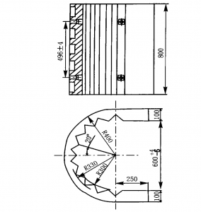
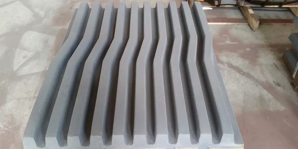
Jaw Plates are the major jaw crusher parts in the machinery. The U-shape Jaw Plate is the parts of PYB 1650 cone crusher, detail drawings, please check below:

Structure drawing of U-shape plate
It’s sizes: 800 mm ×650 mm ×800 mm, thickness:70 mm, weight:850 kg
Casting Processability
The solidification shrinkage rate of high manganese steel is about 615%, and the wall thickness of castings is large, and the tendency of shrinkage cavities is large; the free line shrinkage is 214%~310%, the thermal conductivity is poor, the thermal stress and shrinkage stress are large, and the castings are solidified and cooled. The process is often cracked due to shrinkage. The U-shaped bottom is the stress concentration site where the crack tends to be the largest. The casting body has a U-shaped structure, and the size of the open end is easily exceeded by the deviation of the casting due to the shrinkage deformation of the casting.
Scheme of Foundry Technology
According to the technical requirements and process analysis of castings, the casting process plan is selected as follows: the tooth surface, the installation and the mounting surface are all located on the side. The solution not only guarantees the quality of the casting, but also guarantees the quality of the mounting surface, realizes the principle of sequential solidification, and is advantageous for obtaining dense and sound castings.
In order to ensure the quality of the castings, and at the same time taking into account the convenience of operation, two parting surfaces are established, that is, the upper, middle and lower boxes are divided. The upper box is the riser and the top gate portion, the middle box is the casting cavity portion, and the bottom box is the core head and the bottom gate portion. The upper and lower boxes are ordinary sand box shape, and the middle box is a core shape. In order to ensure the dimensional accuracy of the castings, organic ester hardened water glass self-hardening sand is used, and the surface of the cavity is brushed with alcohol-based magnesia coating.

Scheme of Foundry Technology
Gating system design calculation
According to the processability analysis of castings and the casting performance characteristics of high manganese steel, the design of the gating system follows the following principles: the molten steel must be ensured to enter the cavity uniformly, quickly and smoothly; it is beneficial to control the sequential solidification and the reasonable distribution of the temperature field of the casting; avoid local overheating.
Due to the high height of the casting. Therefore, a stepped gating system is used. That is to say, firstly, the molten steel is fed into the cavity from the bottom runner, and when the molten steel rises to a height, the top gate is then entered into the cavity. It avoids the shortcomings of the molten steel directly impacting the bottom of the cavity, and is beneficial to the exhaust and scum, and also ensures the sequential solidification of the molten steel.
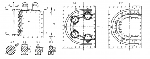
The gating system is placed on the outside of the U-shape. The sprue is located at the bottom of the U-shape, connecting two layers of sprues, and the runner is symmetrical. Both layers of runners are designed to have an annular opening with the same opening direction as the casting opening.
Thereby the overall rigid structure and the shrinkage of the casting are prevented from being hindered. The bottom of the bottom runner is evenly distributed with six internal runners to achieve the purpose of dispersing the hot section and smooth filling. The bottom of the top runner is evenly distributed with four inner gates to enter the cavity from the root of the riser to improve the rise of the riser. Shrink effect.
Pouring system component cross-sectional area
In order to ensure that the molten steel is injected into the cavity from bottom to top, one of the prerequisites is that the total cross-sectional area of each runner must be greater than the cross-sectional area of the sprue to prevent the top runner from being injected prematurely. The molten steel, but the inner runner is too large, the molten steel is easy to inhale the gas and bring in the inclusions, so a suitable open casting system must be adopted, and the ratio of the cross-sectional area of the components is:
∑F包∶∑F直∶∑F横∶∑F内 = 1∶(1. 9) ∶2∶(2. 4)
- ∑F 包= 15. 9 cm2
- ∑F 直= 30. 2 cm2
- ∑F 横= 31. 8 cm2
- ∑F 内= 3812 cm2
Riser system design calculation
One of the conditions for obtaining a dense casting is that the solidification time of the riser should be longer than the solidification time of the casting, that is, to satisfy:
MR ≥1.2 MC
- MR is the modulus of the riser (cm)
- MC is the modulus of the casting (cm)
Expand the casting diagram to approximate the plate-shaped structure, taking the average wall thickness δ = 7.0 cm
MC = 7.0 ÷2 = 3.5 cm
MR ≥1.2 ×3.5 = 4.2 cm
The thermal modulus of the insulated riser is equivalent to 1.3 to 1.4 times the normal riser modulus, and the thermal modulus of the insulated riser is 3.2 cm.
The specification of the insulated riser is «180 mm × 225 mm and its standard mass is 35 kg. In order to facilitate the rise of the riser, the easy-cut riser is adopted.


